
In Situ Thermal Treatment
On this page:
- Schematic
- Introduction
- Other Technology Names
- Description
- Development Status
- Applicability
- Cost
- Duration
- Implementability Considerations
- Resources
Schematic
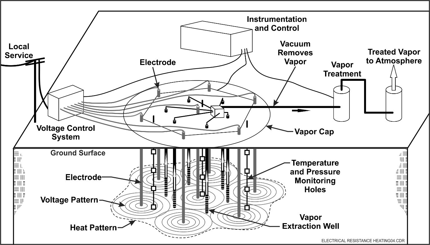
Electrical Resistance Heating System Schematic
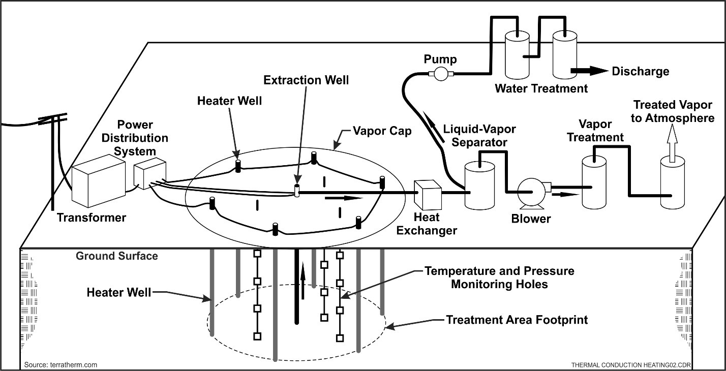
Thermal Conduction Heating System Schematic
Source: TerraTherm.com
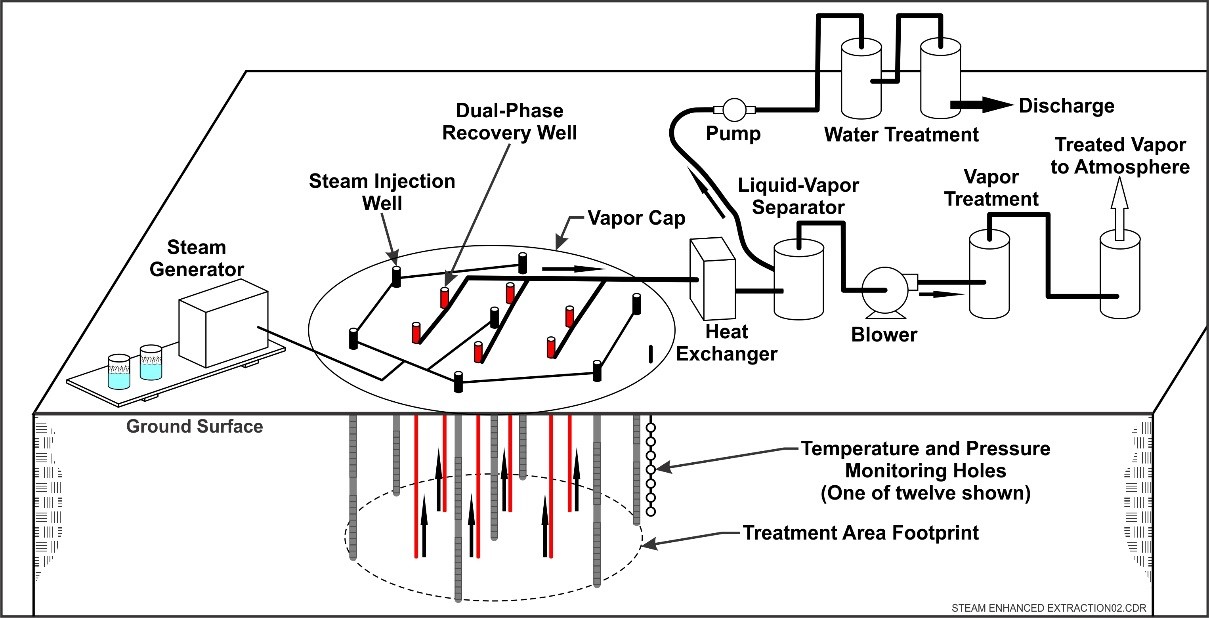
In Situ Steam Flooding Heating System
Introduction
In situ thermal treatment is a general term for three different technologies that are used today – electrical resistance heating (ERH), thermal conduction heating (TCH), and steam enhance extraction (SEE). These technologies can accomplish steam stripping, volatilization, and boiling of volatile organic compounds (VOCs) and semi-volatile organic compounds (SVOCs) from in situ soils and groundwater. In situ thermal treatment is supplemented by vapor collection within the subsurface and aboveground treatment of recovered separated gaseous and liquid phases. For SEE and some implementations of ERH, multiphase extraction is included.
Other Technology Names
Electrical resistivity heating
In situ thermal desorption (ISTD)®
In situ Steam Injection
Three-phase heating®
Description
In situ thermal treatment technologies vary by the method used to deliver heat to the subsurface and the temperature range that can be achieved (and therefore the contaminants that can be treated). However, the overall objective of all methods is to increase the vapor pressure, solubility, and diffusion rates while decreasing the viscosity of liquid contaminants, releasing them from the environmental media, and driving the contaminants to a point of collection for above ground treatment. In situ thermal treatment is sometimes designed as part of a remedy treatment train, with the thermal technology used to treat non-aqueous phase liquid (NAPL) and the highest dissolved concentrations, with other technologies (such as pump and treat, in situ bioremediation or in situ chemical oxidation with persulfate) used as a follow-up process for the dissolved phase plume to ultimately reach cleanup goals. In such cases, the residual heat from in situ thermal remediation may be used to enhance the performance of biodegradation.
- Electrical Resistance Heating (ERH): Electrical resistance heating heats the contaminated soil mass directly using its resistance to electric current. The technology is implemented by placing electrodes in the ground and applying sufficient voltage to produce an electric current which flows through the water in the pore spaces. Resistance to electron flow by the soil releases the energy as heat. The voltage required to heat the subsurface will depend on the conductivity of soil moisture and groundwater in the contaminated zone. Heating vaporizes water from the subsurface, sometimes requiring a continual dripped supply of water to be added around each electrode to maintain adequate electrical conductivity. The maximum temperature that can be achieved by resistive heating is the boiling point of water, which is effective for treating VOCs. During electrical resistance heating, the ground surface is covered by an insulating vapor barrier. As of 2010, ERH was the most commonly implemented in situ thermal remediation technology, outnumbering the implementation of all other thermal treatment technologies by a factor of three (ESTCP, 2010).
- Thermal Conduction Heating (TCH): The thermal well system consists of an arrangement of electrical or gas-fired heating elements placed in vertical wells spaced approximately 7 ft to 15 ft apart and immersed in the contaminated aquifer. The heating elements operate at up to 1,000°C to heat the surrounding soil. Heat transfer from the wells into the soil occurs by simple conduction and through advection (via flowing groundwater or flowing steam). The wells are sometimes installed with an outer perforated screen and their top outlets may be connected to a common manifold. In other cases, the extraction wells are separate from the heating wells. A vacuum applied to the manifold removes air and contaminants for aboveground treatment. The ground surface is covered by an insulating vapor barrier.
- Steam Enhanced Extraction (SEE): SEE uses injected steam to enhance and control contaminant mobility. The injected steam creates a pressure gradient, and the heat reduces the viscosity and density of the organic contaminants. The flow of the injected steam displaces and mobilizes NAPLs toward the extraction wells. As steam is initially injected into the subsurface, heat is transferred to the groundwater and aquifer matrix at the injection site. With continued steam injection, hot water begins to move through the aquifer, driving cooler formation water and contaminants ahead of the hot water front. With continued steam injection, steam itself enters the formation. Steam, water, and any NAPL are collected in multi-phase extraction wells. Steam is considered effective for liquid hydrocarbons having boiling points up to 175°C and has been effective for reducing concentrations of compounds, or mixtures of compounds (such as creosote), with boiling points up to 450°C. In this case, recovery is achieved by reducing the viscosity of the NAPL and displacing it to multiphase extraction wells.
Development Status and Availability
The following checklist provides a summary of the development and implementation status of in situ thermal treatment:
☐ At the laboratory/bench scale and shows promise
☐ In pilot studies
☒ At full scale
☐ To remediate an entire site (source in vadose zone)
☒ To remediate a source only
☒ As part of a technology train
☒ As the final remedy at multiple sites
☒ To successfully attain cleanup goals in multiple sites
In situ thermal treatment is available through the following vendors:
☐ Commercially available nationwide
☒ Commercially available through limited vendors because of licensing or specialized equipment
☐ Research organizations and academia
Applicability
|
Contaminant Class Applicability Rating for In Situ Thermal Treatment (Rating codes: Demonstrated Effectiveness, ◐ Limited Effectiveness, No Demonstrated Effectiveness, ♢ Level of Effectiveness dependent upon specific contaminant and its application/design, I/D Insufficient Data) |
||||||||
|---|---|---|---|---|---|---|---|---|
Nonhalogenated VOC |
Halogenated VOC |
Nonhalogenated SVOC |
Halogenated SVOC |
Fuels |
Inorganics |
Radionuclides |
Munitions |
Emerging Contaminants |
| ● | ● | ● | ● | ● | ○ | ○ | ○ | I/D |
In situ thermal remediation technologies are particularly applicable to sites where short cleanup timeframes are necessary. These technologies also have the advantage of treating many chemical contaminants simultaneously and being less sensitive than other technologies to subsurface heterogeneities. In situ thermal technologies have been used at a wide variety of sites, with a wide variety of hydrogeologic conditions. These technologies can be used above and below the water table, over a wide range of hydraulic conductivities and can be applied under and directly adjacent to occupied buildings. ERH and TCH remediation technologies are not well suited to aquifers with relatively high groundwater flow velocities (greater than approximately 1 foot per day) because of the cooling effect. Ground water controls such as sheet-pile walls or upgradient extraction wells may be necessary. SEE is applicable at higher groundwater flow rates. Sites with abundant conductive debris in the subsurface are also not well suited to ERH.
In situ heating is used primarily to treat high dissolved concentrations of halogenated and nonhalogenated VOCs, gasoline-range fuels, and light/dense non-aqueous phase liquids (LNAPLs/DNAPLs) (USACE, 2014; ESTCP, 2010). VOCs and SVOCs are vaporized by increasing their vapor pressure. Compounds that have a boiling point higher than water (such as tetrachloroethene [PCE]) can still be effectively removed using in situ thermal technologies because the co-boiling temperature of a VOC NAPL in the presence of groundwater is lower than the boiling point temperature of the pure compound. The water vapor and organics generated by heating are collected by multi-phase vacuum extraction wells and separated and treated aboveground. High temperature in situ heating using TCH is used primarily to treat halogenated and non-halogenated SVOCs, polychlorinated biphenyls (PCBs), diesel and oil-range fuels, and DNAPLs (USACE, 2014; ESTCP, 2010).
The feasibility and cost-effectiveness of in situ heating depends upon site hydrogeology and other site conditions. Therefore, it is important to conduct a thorough site assessment to determine the expected outcome of heating and elucidate geological properties (soil type, etc.), hydrologic properties (groundwater flow, degree of saturation, etc.), extent of contamination (the nature and extent of the plume, the extent of the source zone, and locations of known or suspected NAPL), and properties of target contaminants (which is generally available for common contaminants).
Cost
In situ thermal remediation is a very aggressive treatment technology, and the cost to implement it typically is high compared to other less aggressive technologies. In situ thermal technologies are typically selected when treatment time needs to be minimized or when concentrations are very high (especially when NAPL is present). In many cases, in situ thermal remediation may be the only technology that can meet the cleanup objectives. The most critical cost factor is the treatment volume. As with all in situ technologies, application costs vary according to site and contaminants. Major cost drivers include equipment, utilities, and number/spacing of electrodes and vapor recovery wells.
The amount of contaminant mass contained in the in situ thermal treatment zone also has some impact on cost-effectiveness. The higher the contaminant concentrations, the more cost effective in situ thermal technologies become (in terms of dollars per pound of contaminant recovered). Some of the mobilization/demobilization and personnel costs are independent of project size. In addition, these technologies are often associated with specialized vendors and fixed costs are often built into the cost of the operation and maintenance as an equipment lease cost. Major cost drivers include:
Upfront Costs
- Areal extent of contamination and depth of contamination, which affects well and electrode depth and spacing
- Presence of aboveground and below ground metallic structures and utilities
- Need to abandon PVC monitoring wells in the treatment area and install stainless steel or other temperature-resistant metals
- Density of temperature monitoring probes such as thermocouples installed at various locations and multiple depths
- Availability of sufficient electrical capacity at the site or need to upgrade
- Availability of water for ERH and SEE
- Availability and cost of fuel for SEE boiler
Operation and Maintenance Costs
- Treatment technology requirements for extracted liquid and vapor
- Utility rates (electricity and sometimes water)
- Disposal rates for treated liquid and vapor waste
The list above highlights those cost dependencies specific to in situ combustion and does not consider the dependencies that are general to most in situ remediation technologies. Click here for a general discussion on costing which includes definitions and repetitive costs for remediation technologies. A project-specific cost estimate can be obtained using an integrated cost-estimating application such as RACER® or consulting with a subject matter expert.
Duration
Soil remediation by in situ heating typically can be accomplished within six to nine months; however, longer treatment durations may be required at large sites. In many cases portions of the site reach treatment goals prior to other portions of the site and treatment of these areas is discontinued, with operation continuing for an extended period in recalcitrant areas. Treatment duration is site specific and depends on the following conditions:
- Cleanup goals.
- Rate of energy application (power input)
- Volume of in situ media requiring treatment, both areal extent and depth interval
- Contaminant concentrations and distribution
- Hydrogeologic characteristics including groundwater flowrate and variation across the site, depth to groundwater, formation permeability (low permeability materials may take longer to remediate), and anisotropy
- Physical characteristics of contaminants including vapor pressure and Henry's law constant
- Moisture content of the soil
Implementability Considerations
The following are key considerations associated with implementing in situ thermal treatment:
All Described Technologies
- Only a limited number of vendors offer these technologies
- Steam may vent from monitoring wells and subsurface heating can damage buried utilities from both heat and electrical currents. All subsurface artifacts (electrodes, wells, etc.) should be designed and constructed properly so that venting does not occur.
- Utilities may provide a preferential flow pathway for mobilized contaminants to migrate outside of the treatment area, including into buildings. Heating should not be performed near buried utilities.
ERH
- Shallow contaminated areas may result in prohibitively high heat loss to the atmosphere
- For ERH only, moisture must be present in the subsurface in order to allow current flow between electrodes water can be added at low flow rates to allow treatment in unsaturated soil.
- Subsurface heterogeneity can interfere with uniform treatment of in situ media, especially where groundwater flow (and associated cooling effects) is substantially higher in one or more portions of the treatment zone.
- High permeability and hydraulically conductive soils may be more difficult to heat. Additional controls may be required.
- Drying of soil alters soil properties and may cause ground subsidence in areas of thick clays and peat and must be considered during design when this technology is used under buildings or where buildings are planned in the future.
- Performance in extracting less volatile contaminants varies depending upon the maximum temperature achieved - ERH is typically not applicable to SVOCs and heavier-end hydrocarbons.
- High heat of vaporization for water significantly increases the cost and energy footprint especially when the saturated zone is treated.
TCH
- Shallow contaminated areas may result in prohibitively high heat loss to the atmosphereOnly a limited number of vendors offer these technologies
- Subsurface heterogeneity can interfere with uniform treatment of in situ media, especially where groundwater flow (and associated cooling effects) is substantially higher in one or more portions of the treatment zone. (note, though, that heat propagates based on the thermal conductivity which for geologic materials varies over a factor of 3-5 whereas other technologies dependent on fluid flow face fluid conductivities that vary over 5-10 orders of magnitude, so the effect of heterogeneity is much more limited for TCH).
- Drying of soil alters soil properties and may cause ground subsidence in areas of fat clays and peat and must be considered during design when this technology is used under buildings or where buildings are planned in the future.
- Performance in extracting less volatile contaminants varies depending upon the maximum temperature achieved. TCH can achieve temperatures as high as ~350C when applied above the water table, thereby treating SVOCs.
- High permeability and hydraulically conductive soils may be more difficult to heat. Additional controls may be required.
SEE
- Shallow contaminated areas may result in prohibitively high heat loss to the atmosphere, and insufficient overburden pressure to allow suitably high injection pressures.
- Not effective for low-permeability materials (hydraulic conductivity of less than 10-4 cm/sec), though these zones will be heated by conduction.
- Difficult to predict the precise steam migration path in heterogeneous materials, which may result in some zones being less effectively treated than other zones. Low permeability zones that don't directly accept steam and that are less than 10 feet in thickness can be heated by conduction from steam flowing on either side of the zone. Thicker low permeability zones can be heated by combining ERH or TCH with steam injection.
- Not limited by high groundwater flowrate as is ERH or TCH.
Resources
Army Corps of Engineers (USACE). Design: In Situ Thermal Remediation. (2014)
This document provides guidance on screening and selection of in situ thermal treatment technologies, including: steam enhanced extraction, electrical resistivity heating, and thermal conductive heating. The document reviews proper application of the technologies and identifies important design, operational, and monitoring issues.
EPA. Issue Paper: How Heat Can Enhance In Situ Soil and Aquifer Remediation. (1997)
This issue paper contains in-depth information on the properties of some common organic contaminants that affect their movement in and recovery from the subsurface, as well as information on how these properties are affected by temperature.
EPA. Steam Injection for Soil and Aquifer Remediation. Ground Water Issue. EPA 540-S-97-505 (1998)
This issue paper provides basic technical information on the use of steam injection for the remediation of soils and aquifers that are contaminated by volatile or semi-volatile organic compounds.
EPA. In Situ Thermal Treatment of Chlorinated Solvents: Fundamentals and Field Applications. (2004)
This report provides an overview of the principles and science behind the in situ thermal treatment technology; its applicability and general engineering considerations; and applications of the technology through site-specific examples and case studies. Specific technologies include steam-enhanced extraction, electrical resistive heating, and thermal conductive heating.
EPA. CLU-IN Technology News and Trends EPA 542-N-12-005, Issue No. 61 (2012)
This issue of Technology News and Trends highlights IST technologies such as electrical resistance heating, steam enhanced extraction and thermal conduction heating. It provides a list of 18 Superfund sites where IST has been proposed, designed or implemented and contains three featured articles on sites where IST technologies have been used successfully including information on costs.
EPA. A Citizen's Guide to In Situ Thermal Treatment (2012)
This 2-page fact sheet provides an overview of thermal treatment processes, safety, and how this remediation technology might affect the general public. A brief project example is provided.
EPA. Engineering Paper: In Situ Thermal Treatment Technologies: Lessons Learned. (2014)
The purpose of this paper is to convey useful information gained from approximately 10 years of development and deployment of in situ thermal treatment (ISTT) technologies.
EPA. CLU-IN Thermal Treatment: In Situ Technology Profile
A Web page containing an overview of in situ thermal treatment technologies including guidance, applications, training, and additional resources.
EPA. CLU-IN In Situ Thermal Treatment Site Profile Database
This issue paper provides basic technical information on the use of steam injection for the remediation of soils and aquifers that are contaminated by volatile or semi-volatile organic compounds.
ESTCP. Critical Evaluation of State-of-the-Art In Situ Thermal Treatment Technologies for DNAPL Source Zone Treatment. Project ER-200314 (2009)
The project provides a performance assessment of thermal remediation technologies for DNAPL source zone remediation investigations.
Kingston, J.L.T., P.R. Dahlen, and P.C. Johnson. 2010. State-of-the-Practice review of in situ thermal technologies. Groundwater Monitoring & Remediation 30, No. 4/Fall: 64-72.
This issue paper provides basic technical information on the use of steam injection for the remediation of soils and aquifers that are contaminated by volatile or semi-volatile organic compounds.