
Air Sparging
On this page:
- Schematic
- Introduction
- Other Technology Names
- Description
- Development Status
- Applicability
- Cost
- Duration
- Implementability Considerations
- Resources
Schematic
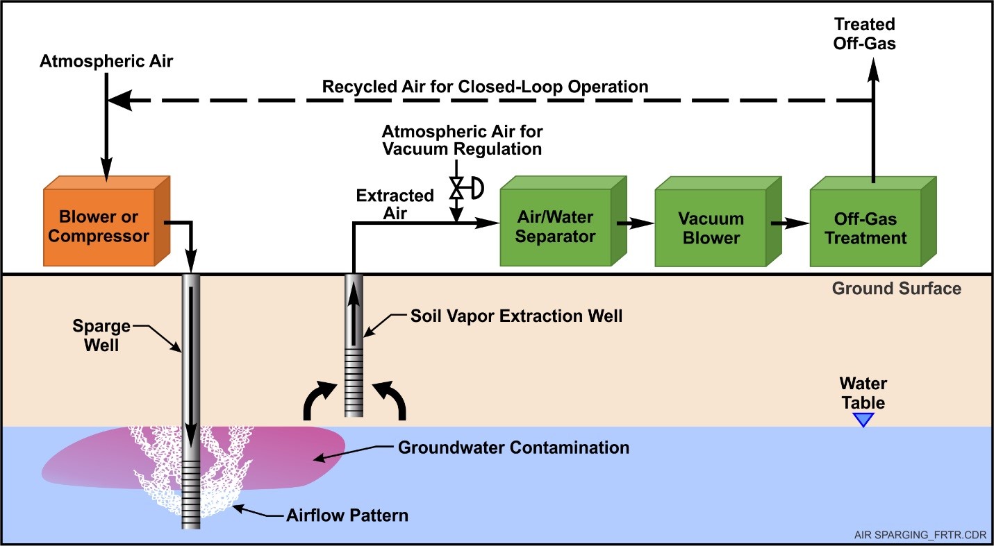
Schematic of Air Sparging
Introduction
Air sparging is a technology used to strip volatile compounds from groundwater and to elevate dissolved oxygen (DO) levels throughout the contaminated zone and stimulate aerobic biodegradation of the contaminants in the aquifer.
Other Technology Names
In situ air sparging (IAS)
Biosparging
Co-metabolic air sparging
Description
Air sparging involves the introduction of air into the aquifer throughout the contaminated zone. The injected air migrates through the soil in discrete channels (not as bubbles) and facilitates removal of volatile organic compounds (VOCs) from the groundwater via stripping or volatilization. It simultaneously delivers oxygen to the groundwater to increase the level of DO, which stimulates biodegradation of the contaminants of concern (COCs). At sites where vapor migration could cause adverse impacts or when required by regulation, air sparging systems are coupled with soil vapor extraction (SVE) systems to recover and treat the vapor. Vapor treatment systems commonly used with SVE include granular activated carbon, thermal or catalytic oxidation, catalytic oxidation, compression/condensation, or internal combustion engine.
Historically, practitioners have installed air sparging systems to: (1) treat immiscible contaminant source zones at or below the capillary fringe; (2) remediate dissolved-phase contaminant plumes; and (3) provide barriers to prevent dissolved-phase contaminant plume migration. Air sparging systems also can be used in conjunction with enhanced bioremediation systems for the delivery of other gases for aerobic biodegradation (e.g., oxygen), anaerobic biodegradation (e.g., hydrogen), and aerobic co-metabolic biodegradation (e.g., propane). Air sparging systems have also been used as a means of improving air distribution for bioventing applications targeting near-capillary fringe soils.
Some practitioners implement a variation of air sparging, referred to as biosparging, in which biodegradation rather than volatilization of contaminants becomes the primary removal mechanism (USACE, 2013). In practice, the term biosparging is frequently used to refer to air sparging systems when the intent is to operate without an SVE system. With biosparging, the goal is to reduce the volatilization rate to a level where an SVE system is not necessary, while maintaining a well-oxygenated treatment zone and a sufficient aerobic biodegradation rate.
Sparge systems require air or sometimes other gases to be introduced and distributed into the aquifer. Typically, air is pressurized using an air compressor; however, when the dissolved-phase contamination is near the water table, a rotary lobe, rotary vane or similar blower can be used (USACE, 2013). The air is then introduced into the aquifer through either vertical or horizontal sparge points. Vertical sparge points are more commonly used; however, horizontal sparge points (directional wells) can be advantageous when aboveground structures are present, which can prevent necessary placement and spacing of vertical points or where the depth to water is large and one horizontal well is less costly than a series of vertical wells. Care must be taken when installing horizontal points to ensure that air is uniformly distributed across the length of the screen. A line of vertical wells provides more flexibility to tailor air flow across a transect.
Early application of air sparging typically was performed by continuously injecting air into all sparge points at the site. However, performance data have indicated that operating sparge points in a pulsed mode (i.e., cycling operation between groups of injection points) improves treatment efficacy. In addition, since pulsing requires fewer sparge points to be operated simultaneously, less air is required, and capital costs are typically less.
At most sites, it is useful to perform a pilot test to gather site-specific data to design and optimize the operation of the full-scale system. Specific information that should be determined includes:
- Injection air flowrate and pressure necessary to achieve appropriate DO concentrations in the target treatment area,
- Lateral extent of air distribution,
- Achievable reductions in COC concentrations
- Concentration of COCs generated in the vadose zone during sparging, and
- Biodegradation rates for the COCs.
Pilot testing consists of first measuring baseline conditions, which include water table elevations and pressures, DO in groundwater, and concentrations of COCs and sometimes oxygen in the soil gas above the water table. In some cases, after collecting baseline data, pump tests can be performed. Air is injected into a sparge point, and a pressure response is measured in nearby monitoring wells. The primary objective of this test is to assess the time required for airflow distribution to come to steady state. Other testing, including tracer testing using helium and sulfur hexafluoride (SF6), neutron probe testing, or electrical resistivity tomography, can be performed to help evaluate air distribution and radius of influence (USACE, 2013).
In lieu of pilot testing, if data indicate that a site would be conducive to air sparging, practitioners sometimes use a standard approach that assumes a conservative 15-foot radius of influence (ESTCP, 2002). The 15-ft spacing recommendation stems from knowledge of air distribution in near-homogeneous and highly permeable aquifer material that yields the most spatially limited air distribution, which is generally not much more than 10 feet in any direction away from the sparge point, assuming the well screen is placed approximately 15 feet below the water table. Hence, a 15-foot spacing generally will provide sufficient distribution of air between sparge points. Note the maximum lateral extent is typically at the water table, so air distribution in three dimensions needs to be considered. Where significant stratification exists in the target treatment zone, a pilot test is recommended.
Development Status and Availability
The following checklist provides a summary of the development and implementation status of air sparging:
☐ At the laboratory/bench scale and shows promise
☐ In pilot studies
☒ At full scale
☒ To remediate an entire site (source and plume)
☐ To remediate a source only
☒ As part of a technology train
☒ As the final remedy at multiple sites
☐ To successfully attain cleanup goals in multiple sites
Air sparging is available through the following vendors:
☒ Commercially available nationwide
☐ Commercially available through limited vendors because of licensing or specialized equipment
☐ Research organizations and academia
Applicability
|
Contaminant Class Applicability Rating for Air Sparging (Rating codes: Demonstrated Effectiveness, ◐ Limited Effectiveness, No Demonstrated Effectiveness, ♢ Level of Effectiveness dependent upon specific contaminant and its application/design, I/D Insufficient Data) | ||||||||
|---|---|---|---|---|---|---|---|---|
Nonhalogenated VOC |
Halogenated VOC |
Nonhalogenated SVOC |
Halogenated SVOC |
Fuels |
Inorganics |
Radionuclides |
Munitions |
Emerging Contaminants |
| ● | ● | ◐ | ◐ | ◐ | ○ | ○ | ○ | ◐ |
Air sparging is effectively applied to treat compounds with moderate to high Henry's Law constants (i.e., high vapor pressure and low solubility) such as halogenated and nonhalogenated VOCs, benzene, etc. (NAVFAC, 2001). It is less effective to treat nonhalogenated semivolatile organic compounds (SVOCs), unless biosparging is the focus. Injection of hydrocarbon gases (e.g. propane, butane) also is possible to enhance biodegradation of chlorinated solvents and 1,4-dioxane (i.e., via aerobic co-metabolic biodegradation). Inorganic compounds and radionuclides cannot be treated using this technology except possibly redox-sensitive inorganics such as iron or arsenic. Air sparging has limited effectiveness for treating mobile non-aqueous phase liquids (NAPLs) resulting from fuel releases (USACE, 2013). However, it can be used to treat various volatile and semi-volatile NAPL constituents such as benzene and naphthalene and will partially remove any residual NAPL that may be present. Volatile NAPLs comprised of short chain hydrocarbons, such as gasoline, tend to be more effectively treated than less volatile NAPLs such as diesel. Even so, the large mass associated with a NAPL plume may take years to volatilize/dissolve, preventing practical application at many of these sites.
Air sparging is best applied to contamination near the water table. Application at sites where low permeability, semi-confining strata are present can create several challenges. For instance, if the COCs are located beneath a semi-confining unit, air injected into this unit could become trapped and/or travel horizontally, potentially facilitating migration of COC vapors or bypass much of the contaminated zone resulting in incomplete treatment. The farther below the water table the target contamination exists, the more likely the diversion of the air channels from the target zone. Also, if COCs are located above and below a low permeability stratum, it may be necessary to install nested sparge points to treat both depth intervals.
Cost
Air sparging is a relatively low-cost technology due to its relative simplicity and maturity. Application costs vary according to the areal extent and depth of contamination. In addition, the need for vapor capture and treatment can significantly increase cost to apply the technology. Major cost drivers include::
Upfront Costs
- Complexity and duration of the pilot test.
- Vapor collection and treatment (if required). Vapor treatment, if required, generally consists of either granular activated carbon or thermal or catalytic oxidation, costs for which vary substantially depending on factors such as volumetric flow rates and types and concentrations of contaminants requiring removal.
- Depth of contamination. Well depth and therefore cost depends strongly on the depth to the water table. Greater pressure is required to introduce air into wells screened at deeper depths beneath the water table, which influences equipment size and cost.
- Areal extent of contamination. Larger plumes will require a greater number of air sparge points.
- Presence of low permeability and semi-confining strata. Low permeability strata can reduce the radius of influence and interfere with gas distribution, thus requiring more wells or nested wells.
- Level of automation. Greater automation may increase capital costs, but may significantly decrease labor costs. Control systems needed for sparging systems are normally not complex.
Operation and Maintenance Costs
- Vapor collection and treatment, if required, necessitate additional labor, utilities, sampling and analytical costs.
- Areal extent of contamination. Larger sites necessitate more sparge points, resulting in greater air requirements and energy.
- Sites at which the depth of contamination beneath the water table is greater will require higher pressures to introduce air and therefore compressor capacity and utility costs are greater.
- Monitoring requirements.
Duration
Air sparging has a medium-term duration typically requiring 3 to 5 years to remediate a site. The duration of operation and maintenance is dependent on the following conditions:
- Cleanup goals
- Contaminant concentration and distribution
- Fraction of total organic carbon and degree of soil saturation
- Aquifer characteristics including permeability and anisotropy
- Henry's Law constant of contaminants
- Air sparge point radius of influence and number of sparge points
- Achievable biodegradation rates
- Diffusion and desorption rates
Implementability Considerations
The following are key considerations associated with applying air sparging:
- Presence of low or impermeable strata, which can prevent contact of air with the contaminated media and/or prevent recovery of the resulting vapor. Inadequate air channel distribution can also limit success due to excessive distances for dissolved contaminants to migrate to the channels (diffusion is required and is a slow process).
- Utility corridors, such as deep sewer lines, may represent an unwanted preferred air path. Vapor intrusion into nearby buildings or utility conduits can be exacerbated by air sparging. Monitoring for vapor intrusion often is required and mitigation (e.g., soil vapor extraction) may be required.
- Groundwater mounding can occur near air sparging wells. Groundwater levels should be monitored during application.
- Although generally not a problem, the introduction of air can cause precipitate or biological fouling on the well screen and/or in the surrounding well packing material.
- Subsurface heterogeneity, which can inhibit uniform air distribution.
- Contaminants with low Henry's Law constants are difficult to treat.
- Changes in the water table depth can significantly affect airflow paths and injection pressures. Typically, a decline in water table will reduce the volume of treatment and lateral reach of the air. Variable water levels can also make balancing airflow into multi-well systems difficult as the pressures needed to overcome the hydrostatic pressure of the water columns in the wells will vary.
- Portions of the sparge point finished aboveground and any associated distribution piping placed aboveground cannot be constructed of polyvinyl chloride pipe due to the potential of splintering should a rupture occur under pressure. High density polyethylene or metallic pipe should be considered.
- It must be possible to inject air at a reasonable flowrate at a pressure below the fracture pressure of the formation, which is a function of overburden pressure (sparge point depth) (USACE, 2013).
- At some sites, vapor recovery and treatment may be required, which increases the complexity of the remedy. Systems may be operated at low flowrates (i.e., biosparging) to eliminate this requirement at some sites, while still achieving acceptable contaminant removal rates.
- Site surface constraints may limit placement of wells or piping in portions of the target zone. This may require alternatives such as directional drilling.
- Generally, higher injection pressures create higher air flows and better distributed air channels as the air can displace water from smaller pores; however, increasing the air flowrate will increase removal up to a certain point at which a diminishing return occurs. At some sites, it may be desirable to intermittently pulse gas into various parts of the site. Operating in this manner can reduce the total volumetric air flowrate and the size of air distribution equipment, while still promoting removal of contaminants through volatilization and biodegradation.
- Using air sparging to create a barrier to treat a dissolved phase plume and prevent further migration can alter the direction of groundwater flow due to partial displacement of water from pores and the resultant loss of transmissivity. Monitoring must be performed to ensure aquifer hydrodynamics are not adversely impacted.
Resources
Environmental Protection Agency (EPA). Air Sparging Web Page
This Web page provides a thorough overview of air sparging, including applications, principles, design, and pros and cons, by the EPA Office of Underground Storage Tanks.
EPA. A Citizen's Guide to Soil Vapor Extraction and Air Sparging (2001)
This fact sheet provides a brief discussion of what SVE and air sparging are and why they are used.
EPA. In Situ and Ex Situ Biodegradation Technologies for Remediation of Contaminated Sites (2006)
This report provides technology descriptions and selection factors for in situ and ex situ biodegradation technologies.
Environmental Security Technology Certification Program (ESTCP). Multi-Site In Situ Air Sparging ER-199808 (2002)
The design paradigm provides details on air sparging principles; site characterization; pilot testing; system design, installation, and operation; and system monitoring. The design paradigm provides guidance for both standard designs, as well as more complex designs, and provides decision points to help the user choose the appropriate level of sophistication for their site.
NAVFAC. Air Sparging Brochure (1999)
Tri-fold brochure on air sparging remediation technology.
NAVFAC. Air Sparging Guidance Document (2001)
This document provides detailed information covering all aspects of air sparging including feasibility analysis, regulatory and permitting issues, pilot testing, system design and construction, operation and maintenance, and site closure.
NAVFAC. Cost and Performance Report Multi-Site In Situ Air Sparging (2005)
The primary performance objective of this study was to implement the air sparging design paradigm at a number of existing air sparging sites and determine whether the design paradigm was effective at evaluating air distribution and whether other design guidelines were valid.
NAVFAC. Guidance for Optimizing Remedial Action Operations (2012)
The objective of this guidance document is to provide information to remedial project managers (RPMs) and their contractors so the techniques can be readily implemented to reduce operating costs while maintaining program effectiveness.
United States Army Corps of Engineers (USACE). In Situ Air Sparging Engineer Manual (2013)
This document provides comprehensive guidance to design and apply air sparging.