
Bioventing
On this page:
- Schematic
- Introduction
- Other Technology Names
- Description
- Development Status
- Applicability
- Cost
- Duration
- Implementability Considerations
- Resources
Schematic
This information may be reproduced without restriction as long as the source attribution is included.
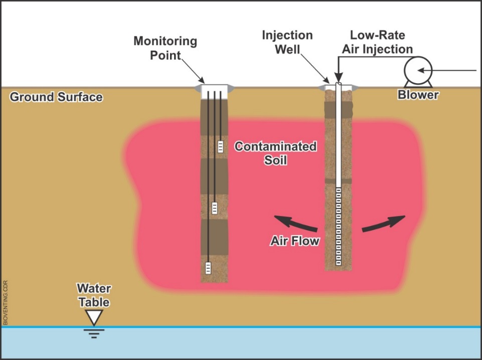
Schematic of Active Bioventing
This information may be reproduced without restriction as long as the source attribution is included.
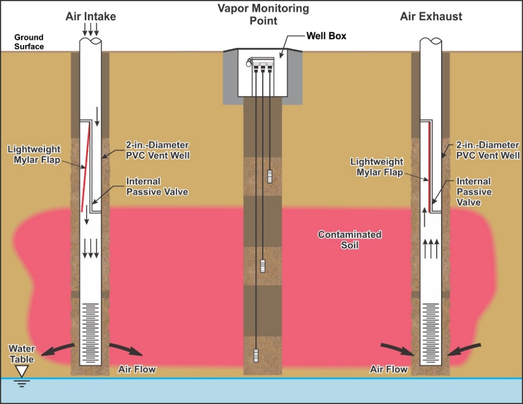
Schematic of Passive Bioventing
Introduction
Bioventing is an in situ treatment technology that involves stimulating indigenous microorganisms through the addition of a gas (typically air) to degrade organic contaminants (typically petroleum hydrocarbons) present in unsaturated soil. Air most often is injected into the vadose zone, but at some sites, can be extracted from the vadose zone. Bioventing generally is performed using blowers, a process referred to as active bioventing. However, at some sites, it may be possible to perform bioventing by relying on barometric changes or tidal fluctuations as opposed to using blowers; this process is commonly referred to as passive bioventing.
Other Technology Names
Active Bioventing
Passive Bioventing
Natural Pressure-Driven Bioventing
Cometabolic Bioventing
Anaerobic Bioventing
Description
Bioventing involves the introduction of a gas into the unsaturated zone to enhance the biodegradation of a contaminant by indigenous microorganisms. The most common application of bioventing is to introduce air to increase the oxygen concentration to greater than 5 percent to stimulate biodegradation of petroleum hydrocarbon contamination, although other less common applications such as anaerobic and cometabolic bioventing to treat chlorinated ethenes have been reported in the literature (EPA, 2006). As such, this profile is primarily focused on the application of bioventing to treat petroleum hydrocarbons.
The most common bioventing approach is to use one or more blowers to introduce air into the vadose zone (referred to as active bioventing). The blowers can be operated to either inject air or extract soil vapors from a series of vent wells. When extracting vapors, removal of the gas creates a negative pressure that causes atmospheric air to be drawn into the subsurface. Both methods are equally effective at treating the vadose zone. However, extraction minimizes (or eliminates) vapor intrusion into nearby buildings, whereas injecting air can exacerbate vapor intrusion due to increased subsurface pressure and creation of preferential pathways. At many sites, vapor treatment using thermal or catalytic oxidation or granular activated carbon (GAC) may be required during the initial months of operating a system designed for extraction of soil gas. Although the extraction mode of operation may appear to be similar to soil vapor extraction (SVE), an important difference is that the bioventing system is operated at low flowrates with the objective of increasing the concentration of oxygen in the vadose zone, whereas SVE systems are designed to operate at high flowrates to volatilize the contaminants (USACE, 2002). The use of low-flow vapor extraction to increase oxygen content faces difficulties to introduce oxygen-rich air from the surface to deep target soils at a rate that will support acceptably rapid biodegradation. Injection of air, on the other hand, can directly deliver the oxygen-rich air to the immediate vicinity of the target soils.
Less common is the use of passive bioventing systems in which changes in atmospheric pressure and, in rare situations (e.g., sites where tidal fluctuations are pronounced) changes in groundwater levels facilitate the introduction of ambient air into the vadose zone. Vent wells equipped with specially-designed valves that allow fresh air to enter the well during high pressure conditions are used to facilitate the exchange of gases.
Vent wells used for either active or passive approaches are generally constructed of Schedule 40 polyvinyl chloride (PVC) pipe and screen. The bottom portion of the screen should be placed somewhere between the lowest and highest anticipated groundwater table level if the contamination extends to the water table, otherwise the screen should extend to a small distance below the base of the target treatment zone. The shallow end of the screen should be placed no more than 1 to 3 feet above the contaminated interval. There is no limit on screen length; however, care should be taken to ensure that the gas is delivered across the entire target treatment depth and does not preferentially flow into shallow or more permeable zones. Vent wells can include short lengths of screen installed at discrete depths in different lithologic units to facilitate air distribution if zones of varying permeability are present.
Soil gas monitoring points are installed to monitor changes in subsurface pressures and concentrations of oxygen, carbon dioxide, and total petroleum hydrocarbons (TPH). The points generally are comprised of short lengths of multiple narrow diameter screens (e.g., 1-inch-diameter by 4-inch-long), each connected to tubing installed in a single borehole. The borehole is backfilled with sand across the screened interval and with hydrated bentonite between the sand intervals to prevent short-circuiting of vapors. A bioventing pilot test is recommended to evaluate the volume of influence of a vent well and to evaluate initial degradation rates and vapor treatment requirements (if extraction is performed). The test is performed by injecting or extracting air into a vent well at one or more flowrates and measuring changes in subsurface pressure, oxygen, and carbon dioxide as well as measuring TPH concentration changes in soil gas monitoring points installed at various distances radially outward from the vent well. Simple scatter plots and cross sections of the resulting data (distance versus oxygen and contaminant concentrations) can be created to determine a volume of influence for the full-scale application. The pressure measurements provide insights on the air flow paths, but a pressure response does not ensure that oxygen would be delivered to those locations.
In situ respiration tests are performed periodically during application of the full-scale remedy. A baseline test is performed immediately prior to or at the beginning of treatment and additional tests can be performed quarterly to annually thereafter to evaluate change in degradation rates over time. The test is initiated by turning off the bioventing system after air has been introduced into the vadose zone for at least 24 hours. Concentrations of oxygen, carbon dioxide, and petroleum hydrocarbons are measured over one to five days. The test is usually concluded when the oxygen concentration drops to below 5 percent. Measurements are taken frequently during the first day of monitoring but can be spaced at greater intervals during later days. In general, if the petroleum fuel source is easily biodegradable (e.g., fresh gasoline), then measurements must be taken at relatively short intervals, and the test duration will be less than if the source is difficult to degrade (e.g., weathered motor oil), requiring longer test duration and generally longer intervals between measurements. The biodegradation rate can be calculated based on the oxygen or carbon dioxide utilization rate. However, using carbon dioxide may not be as reliable at sites having alkaline soil conditions since high pH can convert carbon dioxide to a mineral carbonate (AFCEE, 2004).
Development Status and Availability
The following checklist provides a summary of the development and implementation status of bioventing:
☐ At the laboratory/bench scale and shows promise
☐ In pilot studies
☒ At full scale
☐ To remediate an entire site (source and plume)
☒ To remediate a source only
☒ As part of a technology train
☒ As the final remedy at multiple sites
☒ To successfully attain cleanup goals in multiple sites
Bioventing is available through the following vendors:
☒ Commercially available nationwide
☐ Commercially available through limited vendors because of licensing or specialized equipment
☐ Research organizations and academia
Applicability
|
Contaminant Class Applicability Rating for Bioventing (Rating codes: Demonstrated Effectiveness, ◐ Limited Effectiveness, No Demonstrated Effectiveness, ♢ Level of Effectiveness dependent upon specific contaminant and its application/design, I/D Insufficient Data) |
||||||||
|---|---|---|---|---|---|---|---|---|
Nonhalogenated VOC |
Halogenated VOC |
Nonhalogenated SVOC |
Halogenated SVOC |
Fuels |
Inorganics |
Radionuclides |
Munitions |
Emerging Contaminants |
| ● | ○ | ● | ○ | ● | ○ | ○ | ○ | ♢ |
Conventional bioventing techniques are used primarily to treat aerobically biodegradable compounds such as petroleum hydrocarbon constituents including volatile organic compounds (VOCs) and semi-volatile organic compounds (SVOCs). Fuels that have been remediated successfully include gasoline, jet fuels, kerosene, and diesel fuel. However, bioventing is most often used at sites with mid-weight petroleum products (i.e., jet fuel), because lighter products (i.e., gasoline) tend to volatilize readily and can be removed more rapidly using SVE (EPA, 1994). For heavier hydrocarbons (e.g., weathered diesel-range organics), standard bioventing should be applied only when the subsurface is actually oxygen-limited.
Cometabolic bioventing involves the injection of a cometabolite such as methane or propane that is metabolized by bacteria. The metabolism causes the expression of enzymes (often oxygenases) that fortuitously react with the chlorinated VOC. Cometabolic bioventing may be applicable to contaminants such as trichloroethylene (TCE), trichloroethane (TCA), ethylene dibromide, and dichloroethylene (DCE) that resist direct aerobic degradation (EPA, 2006). Anaerobic bioventing is an emerging technology used to treat chlorinated compounds (e.g., PCE, TCE, PCP), some polychlorinated biphenyls (PCBs), and pesticides (e.g., lindane and DDT) (EPA, 2006). In place of air injection, anaerobic bioventing delivers nitrogen gas and an electron donor (e.g., hydrogen) to the subsurface.
Cost
Bioventing is a relatively low cost technology because it generally is not equipment intensive, requires little supporting infrastructure and utilities, and monitoring requirements tend to be minimal. Costs are highly dependent on the treatment area, depth of contamination, and soil lithology, which influence the number and design of blowers, vent wells, and soil gas monitoring points. Major cost drivers for bioventing can be divided into two categories including upfront costs and operation and maintenance costs. These cost categories along with some of the more common factors that impact individual cost components include:
Upfront Costs
- Design and extent of a pilot study. Studies can be designed using as few as one vent well operated for a few days to estimate volume of influence to more involved studies using multiple wells operated over extended periods to evaluate degradation rates, concentrations in vapor (extraction test) and other parameters.
- Areal footprint and lithology of contaminated soil. A greater number of vent wells and soil gas monitoring points is required at larger sites, impacting well installation cost. The volume of influence is less in tight soils or in soils with high residual moisture content. Air injection/extraction rate will be greater at larger sites necessitating a greater number and/or larger blowers.
- Vapor treatment. The need for vapor treatment is based on the mode of operation and the type of contaminants of concern present. If an extraction system is used, vapor treatment, which may consist of catalytic or thermal oxidation or GAC, may be required, especially if the fuel source is a lighter fuel such as gasoline or JP-4 jet fuel. Many times portable oxidizer units are leased during the initial months of operation and transitioned to less costly treatment or no treatment as concentrations decrease over time. The need for (and cost of) vapor treatment typically discourages the use of the extraction mode for bioventing.
- Site location. Subsurface installation of extraction/injection manifolds may be required at sites located in heavy vehicular or pedestrian traffic areas.
Operation and Maintenance Costs
- Treatment duration. Treatment duration impacts the following:
- Equipment lease duration (e.g., blowers, compressor, tanks, generator). Cost will depend on size and complexity of injection system; contaminants of concern; air injection rate; injection gas storage requirements (for anaerobic venting only); and access to utilities.
- Utilities. Costs will vary depending on utility rates (electric and diesel); site size; equipment size; and air injection rate and the type of vapor treatment required (if any).
- Number of required monitoring events.
- Amendments. Additional primary substrate (for cometabolic venting only); or injection gas (for anaerobic venting only). Costs will vary depending on substrate injection requirements and rates; and anaerobic gas injection rates and requirements.
- Labor (for operating the system and sampling analysis for process control). Costs will vary depending on system complexity; and supervisory and site quality assurance and health and safety support requirements.
- Long-term monitoring for process control. Costs will vary depending on remedial goals, performance criteria, and site footprint.
The list above highlights those cost dependencies specific to bioventing and does not consider the dependencies that are general to most in situ remediation technologies. Click here for a general discussion on costing which includes definitions and repetitive costs for remediation technologies. A project-specific cost estimate can be obtained using an integrated cost-estimating application such as RACER® or consulting with a subject matter expert.
Duration
Bioventing is a medium- to long-term technology. Typical cleanup can range from 6 months to 5 years. The duration of operation and maintenance is dependent on the following conditions:
- Cleanup goals.
- Type of contaminants. In particular, weathered fuels and fuel sources comprised of longer-chain hydrocarbons (e.g., motor oil) may degrade much slower than fresh sources or sources comprised of mostly shorter chain hydrocarbons (e.g., gasoline) and may be limited by low solubility and generally contain less mobile constituents.
- Contaminant concentration and distribution.
- Achievable biodegradation rates.
- In situ characteristics including permeability and anisotropy, which can impact ability to adequately and uniformly distribute the gas to the vadose zone.
Implementability Considerations
The following factors may limit the implementation and effectiveness of bioventing:
- The presence of the water table within several feet of the surface can reduce bioventing performance and would not be a good application for the technology.
- Vapors can build up in basements or other structures within the radius of influence of air injection wells, a problem that can be alleviated by extracting air near the structure of concern.
- Subsurface heterogeneity can interfere with efficient aeration of the contaminated zone.
- Low-permeability and high-moisture content soils are difficult to treat due to insufficient aeration.
- Low soil moisture content may limit biodegradation and the effectiveness of bioventing, which tends to dry out the soils.
- At sites where high concentrations of lighter end petroleum products (e.g., gasoline, JP-4) are present and/or the source of contamination is fresh, SVE in lieu of or prior to bioventing should be considered.
- Vapor monitoring at the soil surface may be required when soils are aerated through air injection.
- Aerobic biodegradation of many chlorinated compounds may not be effective unless either a primary substrate is present or an anaerobic cycle is used.
- Low ambient temperatures, such as those found in arctic environments, can significantly decrease biodegradation rates.
- Contamination is located in an area that is not easily accessible (e.g., underneath buildings). This may limit the ability to install bioventing wells. More expensive horizontal wells may be required.
- Contamination is widespread and/or deep, which can result in high well installation cost.
- A fluctuating water table with hydrocarbon contamination can re-contaminate soil treated by bioventing extending remedial timeframes.
Resources
AFCEE. Procedures for Conducting Bioventing Pilot Tests and Long-Term Monitoring of Bioventing Systems (2004)
Provides guidance for site selection, planning, monitoring, and closure.
EPA and AFCEE. Manual Principles and Practice of Bioventing, Volume I - Principles and Volumes 1 and 2 - Bioventing Design (1995)
Provides results of a multi-site demonstration that evaluated the efficacy of bioventing under a wide range of site conditions. Theoretical basis for aerobic bioventing, design guidance, and case studies are provided.
EPA. Bioventing. Chapter III How to Evaluate Alternative Cleanup Technologies for Underground Storage Tank Sites: A Guide for Corrective Action Plan Reviewers (2017)
Description of bioventing, its effectiveness and design principles.
EPA. Engineering Issue: In Situ and Ex Situ Biodegradation Technologies for Remediation of Contaminated Sites (October 2006)
Provides descriptions of bioventing and other related technologies.
EPA. Engineering Issue: In Situ Treatment Technologies for Contaminated Soil (November 2006)
Provides a discussion of applicability and limitations of aerobic, anaerobic, and cometabolic bioventing.
ESTCP Natural Pressure-Driven Passive Bioventing
Presents results from technology demonstration of passive bioventing. It includes links to the final project report, addendum, guidance document and cost and performance report.
NAVFAC. Passive Bioventing in Stratified Soils and Shallow Groundwater Conditions, TDS 2083 (August 2000)
Describes the passive bioventing process where gases moving naturally in and out of the vadose zone provide enough oxygen for biodegradation, rather than using a blower to inject or extract air.
U.S. Army Corps of Engineers (USACE). Engineering and Design Soil Vapor Extraction and Bioventing (2002)
Provides practical guidance for the design and operation of SVE and bioventing systems.