
Vapor Treatment Technologies
On this page:
- Schematic
- Introduction
- Other Technology Names
- Description
- Development Status
- Applicability
- Cost
- Duration
- Implementability Considerations
- Resources
Schematic
This information may be reproduced without restriction as long as the source attribution is included.
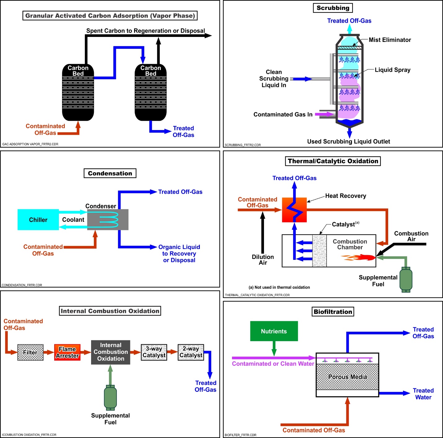
Schematic of Common Vapor Treatment Technologies
Introduction
A number of in situ remediation technologies including soil vapor extraction (SVE), thermal treatment, in situ combustion, bioventing, and multiphase extraction as well as ex situ technologies such as air stripping, thermal desorption, incineration, biopiles, and composting generate a vapor stream that may require treatment depending on contaminant type and concentration, site location, and regulatory requirements. In addition, technologies such as enhanced in situ reductive dechlorination or in situ chemical oxidation have the potential to generate gases, which may need to be recovered and treated to prevent vapor intrusion into nearby buildings. A variety of treatment options based on physical (adsorption and condensation), chemical (oxidation), and biological (biodegradation) processes are available to treat the vapors generated by these remediation technologies. These treatment technologies can be applied independently or as part of a treatment train to overcome site-specific limitations and remove a wide-range of contaminants of concern (COCs) than possible using a single treatment technology. Each type of treatment has its advantages and limitations and may or may not be applicable to all COCs at a site. This technology profile describes commonly used vapor treatment technologies, presents their basic principles and applicability, and describes their limitations and other considerations for implementation.
Other Technology Names
Off-gas treatment
Vapor phase treatment
Gas phase treatment
Description
Vapor treatment is accomplished using a variety of technologies that are based on the type of unit operation process employed. Common classes of treatment include:
Adsorption — Adsorption is the adhesion of molecules of COCs to the outside or inside portion of a media. Adsorption can be physical (physisorption) or chemical (chemisorption). Physisorption relies on weak binding forces to adhere the COC to the surface of the media, which can be reversed (desorption) when an outside force (e.g., heat) is applied. Chemisorption results in a much stronger bond between the COCs and the sorbent media. A reaction occurs that chemically alters the media and COCs, creating a permanent bond that prevents desorption from occurring (EPA, 2017). The term adsorption is often used to refer to physisorption as this is more common for off-gas treatment.
Vapor phase granular activated carbon (GAC) is the most common type of adsorption media available for treatment of vapor generated by remediation technologies. Treatment is performed by passing a vapor stream through one or more vessels containing activated carbon, which removes contaminants by (physi)sorption until available active sites are occupied. Carbon is "activated" for this purpose by being processed to create porous particles having a large internal surface area (300 to 2,500 square meters or 3,200 to 27,000 square feet per gram of carbon) that attracts and adsorbs organic molecules as well as certain metal and inorganic molecules. The carbon typically is placed in packed beds, installed in series and/or in parallel, through which the contaminated air flows until the concentration of contaminants in the effluent from the carbon bed exceeds an acceptable level. Units are typically installed in series to provide a safety factor against breakthrough above regulatory discharge or risk-based levels (commonly referred to as a "lead/lag configuration"), but also can be installed in parallel to increase flow throughput. Granular or pelletized activated carbon generally is used for off-gas treatment applications because of the low pressure drop, high mechanical strength, and low dust content. Once a COC breaks through a GAC unit above a pre-determined level, it is considered "spent," and must either be regenerated for reuse or sent off site for disposal. The carbon can be regenerated in place, regenerated at an off-site commercial regeneration facility, or disposed of at a permitted thermal treatment (e.g., incineration, cement kilns) or landfilling facility, depending upon economic considerations. Vapor phase GAC is commonly used because of its simplicity and low capital cost. If COC concentrations are high or any of the COCs have poor adsorptive characteristics, the use of vapor phase GAC can become very expensive over time.
Biodegradation — Biodegradation of COCs is performed by passing the vapor stream through a biofilter consisting of a bed of porous support media, on which the COCs partition into a thin water film on the media and are degraded by microorganisms. The microorganisms within the biofilm degrade the organic contaminants to harmless end products such as carbon dioxide and water, plus mineral salts such as sulfur, nitrogen, and chloride. Contaminated air is introduced into the bottom of the biofilter and moves up through the media pore spaces and over the biofilm surface. The biofilter media can consist of natural materials such as peat, wood chips, compost, sludge, sand, and soil or engineered materials such as vermiculite, GAC, and diatomaceous earth pellets. Specialized materials such as oyster shells also may be used to help control pH. Use of biofiltration is limited to treating those COCs that are amendable to biodegradation and it is important to maintain necessary conditions (i.e., pH, moisture content, temperature) for the microorganisms to proliferate. For instance, to ensure the healthy growth of microorganisms, the biofilter is typically sprayed with water and nutrients to keep the filter material moist and a polyvinyl chloride (PVC) liner is added to collect leachate. Specific strains of bacteria may be introduced into the filter and optimal conditions provided to preferentially degrade specific compounds. The use of an adsorptive media such as GAC allows the contaminants to be quickly adsorbed and subsequently biodegraded within the biofilter. Biofiltration is prone to biofouling since the conditions needed to promote degradation of COCs also are conducive to the growth of other organisms (e.g., fungi). Although this vapor treatment technology is well-developed for composting and odor control operations, it is not widely used for environmental remediation applications.
Condensation — Condensation is an off-gas treatment technology used to remove condensable organics from a non-condensable gas stream by reducing the stream temperature and/or increasing pressure. Condensation is primarily used at sites employing in situ thermal treatment (such as steam or electrical resistance heating) where heating of the subsurface significantly increases the contaminant concentrations in vapor. It is not commonly used for off-gas treatment at sites where the remediation technology creates a vapor stream at near ambient temperatures and pressures (e.g., soil vapor extraction), but has been used at a small number of sites with extremely high COC concentrations and/or presence of light non-aqueous phase liquids (LNAPL). Condensation is typically employed for very high influent concentrations and/or complex mixtures of many COCs that cannot be treated by other methods due to technical feasibility or excessive costs. For these high influent mass loading conditions, the disposal or recycling costs associated with condensation treatment are less than the operation and maintenance (O&M) costs for other air treatment technologies.
Organic vapor condensation from a gas stream may be performed by lowering the gas stream temperature at a constant pressure in a heat exchanger or increasing the gas stream pressure at a constant temperature (or a combination of both). There are two common types of condensers: surface and direct contact. Surface condensers are generally shell-and-tube heat exchangers, where coolant flows inside the tubes to condense the water and organic compounds in a gas stream flowing outside the tubes. Contact condensers operate by spraying a cool liquid directly into a gas stream which condenses the organics. In both types of condensers, the water will be saturated with volatile organic compounds (VOCs). For lower solubility VOCs, this mixture can be separated for recycling and reuse; or alternatively, the mixture can be treated on site or shipped off site to a commercial recycling or disposal facility. Coolants used to condense organics include chilled water, brine solutions, and cryogenic fluids (e.g., liquid nitrogen). One advantage of using a vapor condensation system for off-gas treatment is that such a system is quite safe, even when applied to vapor streams in which the concentration of VOCs approach or exceed a lower explosive limit (LEL) condition.
Oxidation — Oxidation relies on elevated temperatures to convert organic COCs in the vapor stream to carbon dioxide and water. Several types of oxidation units are available including thermal, catalytic, and photocatalytic. Thermal oxidizers generally are operated between 760 and 870°C (1,400 and 1,600°F). Catalytic oxidizers incorporate a precious metal catalyst (e.g., platinum/palladium), which facilitates the reaction and permits the unit to operate at a lower temperature (320° to 540°C [600° to 1,000°F]) while maintaining a high removal efficiency. Thermal oxidizers can often be converted to catalytic units after initially high influent COC concentrations decrease to less than 1,000 to 5,000 parts per million by volume (ppmv). Photocatalytic oxidation, which is not commonly used for environmental treatment applications because of its cost and other operating complexities, employs ultraviolet light generated by bulbs in conjunction with a catalyst (e.g., titanium dioxide) to oxidize COCs at ambient temperature. Because photocatalytic oxidation relies on ultraviolet (UV) light to break chemical bonds, it is more difficult to achieve complete oxidation to carbon dioxide and water, and byproducts can be created depending on the types of organic compounds that are treated.
Thermal and catalytic oxidation units can be operated using the heat of oxidation to preheat and partially oxidize the vapor stream before it enters the main combustion chamber to reduce the cost of supplemental fuel usage. Regenerative oxidizers use a ceramic bed heated from a previous oxidation cycle to heat the gases, whereas recuperative oxidizers pass the hot effluent vapor through a heat exchanger, which preheats the gases at the entrance of the oxidizer. If gasoline is a co-contaminant, heat exchanger efficiencies are limited to 25 to 35%, and preheat temperatures are maintained below 180°C (530°F) to minimize the possibility of ignition occurring in the heat exchanger. In addition, flame arrestors are always installed between the vapor source and the thermal oxidizer.
Internal combustion engines (ICE) and flameless thermal oxidizer systems are specific types of oxidation systems that can be used to treat vapor streams with high concentrations (up to 30% by volume) of total petroleum hydrocarbons (TPH) from multi-phase extraction or soil vapor extraction systems where significant LNAPL mass is present, and treatment by other methods is either not technically feasible or is cost prohibitive. This level of TPH emissions can exceed LEL conditions and/or loading limits for thermal and catalytic systems (i.e., requires significant dilution with clean air), which in turn can pose safety concerns.
An ICE is essentially an automotive engine. ICE units are designed to accept petroleum hydrocarbons in the vapor phase rather than in the liquid phase. Each ICE unit is equipped with a valve that bleeds in ambient air to maintain the required fuel/air mixture, because the soil vapor may contain very low concentrations of oxygen, especially during the initial stages of operation. Ambient air is added to the engine through an intake valve at a ratio sufficient to bring the oxygen content up to the stoichiometric requirement for combustion.
In a flameless thermal oxidizer system, the influent gas, ambient air, and auxiliary fuel are pre-mixed prior to passing the combined gaseous mixture through a pre-heated inert ceramic media bed. Through the transfer of heat from the ceramic media to the gaseous mixture, the organic compounds in the gas are oxidized to carbon dioxide and water. Flameless thermal oxidizers are designed to operate safely and reliably above the LEL condition while maintaining a constant operating temperature.
ICEs and flameless thermal oxidizer units are capable of destruction efficiencies of greater than 99%. Tests of destruction of benzene, toluene, ethylbenzene, and xylenes (BTEX) components by ICE treatment show that non-detectable levels of contaminants can be achieved in the exhaust gas, and outlet contaminant concentrations below 1 ppm can be achieved in many cases. At sites where TPH concentrations are very high, very little supplemental fuel may be required, resulting in a more favorable operation cost.
Oxidation units may be fixed or trailer-mounted depending on the size of the unit, anticipated treatment duration, and terrain. Thermal and catalytic units are generally powered by natural gas or propane, while photocatalytic oxidizers require electricity to operate the UV bulbs. ICE units are partially powered by the hydrocarbons in the influent stream, but are also configured to use supplemental natural gas or propane.
Scrubbing — Scrubbing is performed using a diverse class of vapor treatment equipment (scrubbers) to remove particulate matter, neutralize acidic gases, and remove various sulfur compounds. Scrubber is a general term that describes use of physical or chemical absorption to remove pollutants from a process gas stream. Scrubbers commonly are used in power production, wastewater treatment, and other industrial facilities. Scrubbers are used at hazardous waste sites in conjunction with thermal or catalytic oxidizers that involve the treatment of chlorinated organic contaminants. The oxidation of chlorinated organics produces hydrochloric acid (HCl) vapors, and if the acid levels are high, scrubber treatment is necessary to neutralize the generated HCl, which can aggressively corrode piping and other structures prior to the stack discharge.
Two broad classifications of scrubbers include wet scrubbers and dry scrubbers. In a wet scrubber, a liquid absorbent is contacted with the gas stream in a vessel and can utilize media packing to serve as the surface area for contact and absorption between the liquid and gas streams. Wet scrubbers remove contaminants using physical and chemical processes such as inertial or diffusional impaction, reaction with a sorbent or reagent slurry, or absorption into a liquid solvent. These types of scrubbers can be used to control particulate matter and certain types of vapor phase contaminants such as various acids, hydrogen sulfide, sulfur dioxide (SO2), ammonia, chlorides, and acids (e.g., hydrochloric, nitric, and sulfuric). For treating acid gas streams such as HCl, a neutralization liquid (e.g., sodium hydroxide) can be used as the absorption stream. A wide range of wet scrubbers, having very different configurations, are commercially available and include orifice, venturi, fiber-bed, mechanical, impingement plate, spray, and condensation scrubbers. The added liquid must be removed periodically and disposed.
In a dry scrubber, which is typically used to neutralize an acid gas stream, a lime absorbent (e.g., a lime slurry) is injected or introduced into the treatment vessel in a manner that allows direct contact with the acid gas stream to allow for absorption and neutralization. Sulfur can also be removed from flue gas using an atomized lime slurry. Similar to wet scrubbers, dry scrubbers also come in a range of configurations.
Development and Implementation Status
The following checklist provides a summary of the development and implementation status of vapor treatment technologies:
☐ At the laboratory/bench scale and shows promise
☒ In pilot studies
☒ At full scale
☐ To remediate an entire site (source and plume)
☐ To remediate a source only
☒ As part of a technology train
☐ As the final remedy at multiple sites
☐ To successfully attain cleanup goals in multiple sites
Vapor treatment technologies are available through the following vendors:
☒ Commercially available nationwide
☒ Commercially available through limited vendors because of licensing or specialized equipment
☒ Research organizations and academia
Applicability
| Vapor Treatment Technology |
Contaminant Class Applicability Rating for Vapor Treatment (Rating codes: Demonstrated Effectiveness, ◐ Limited Effectiveness, No Demonstrated Effectiveness, I/D Insufficient Data, N/A Not Applicable) | ||||||||
|---|---|---|---|---|---|---|---|---|---|
Nonhalogenated VOC |
Halogenated VOC |
Nonhalogenated SVOC |
Halogenated SVOC |
Fuels |
Inorganics |
Radionuclides |
Munitions |
Emerging Contaminants | |
| Adsorption (carbon) | ● | ● | ● | ● | ● | ◐ | ◐ | N/A | I/D |
| Biofiltration | ● | ◐ | ◐ | ◐ | ● | ○ | ○ | N/A | I/D |
| Condensation | ● | ● | ● | ● | ● | ○ | ○ | N/A | I/D |
| Oxidation (thermal & catalytic) | ● | ◐ | ● | ◐ | ● | ○ | I/D | N/A | I/D |
| Oxidation (ICE) | ● | ○ | ● | ○ | ● | ○ | ○ | N/A | I/D |
| Scrubbing (wet) | ○ | ○ | ○ | ○ | ○ | ● | ● | N/A | I/D |
| Scrubbing (dry) | ● | ○ | ○ | ○ | ○ | ● | I/D | N/A | I/D |
Vapor treatment technologies are applicable to those types of contaminants that are expected to volatilize and be present in a vapor stream including fuels, VOCs, and semi-volatile organic compounds (SVOCs), and some metals (e.g., methyl mercury and organic lead such as tetraethyl lead), or may be generated as a byproduct of treatment (e.g., particulates, hydrochloric acid). Vapor treatment technologies are not considered applicable to fuels, since fuels are LNAPLs, and by definition are not present in the vapor stream. However, LNAPLs contribute to COCs present in the vapor stream through volatilization during restoration activities to form high concentrations of VOCs and SVOCs, which can be effectively treated by GAC, thermal oxidation, condensation, and biofiltration technologies. Commonly encountered munitions constituents (e.g., perchlorate, trinitrotoluene [TNT], and royal demolitions explosive [RDX]) have very low vapor pressures and therefore are not encountered in vapor streams.
Adsorption capacity of GAC depends on the properties of the contaminants, as well as the material used to develop the GAC (e.g., coconut husks, wood, bamboo, coal). Larger non-polar molecules with lower water solubilities and higher octanol/water coefficients tend to adsorb more strongly than smaller polar, molecules like vinyl chloride. The material used to produce the GAC (e.g., coconut husks, wood, bamboo, coal) and its associated surface area also impact the ability of the GAC to absorb contaminants, with smaller size and greater surface area providing better sorption capacity (but higher pressure drop across the treatment vessel).
Impregnated carbon is also used to improve target contaminant removal, such as sulfur- and iodine-impregnated carbon for mercury removal, KMnO4-impregnated carbon for VOC removal (particularly vinyl chloride), and potassium hydroxide for hydrogen sulfide removal. GAC tends to be most effective at concentrations that are lower than those that can be effectively treated with oxidation, ranging from a few to a few hundred ppmv. Higher concentrations can be treated, but additional residence time and media may be needed, and more frequent change-outs due to breakthrough may be required. Treatable concentrations are highly dependent on the types and quantities of each of the COCs in the vapor stream and the specific type of carbon used. High concentrations of ketones can be a fire hazard as combustion can initiate due to heat of adsorption. In some cases, fire suppression systems may be required. The GAC vendor should be consulted during design, especially with an unusual contaminant or a mixture of contaminants with varying sorption properties, and will determine the volume and type of material necessary based on site-specific conditions.
Oxidation technologies are very effective at removing most organic compounds; however, care must be taken when certain COCs such as chlorinated organics are present in the vapor stream that may need to be accounted for in the vapor treatment system design. Although these technologies can remove limited quantities of chlorinated organics, HCl is a byproduct of the reaction, which over time can cause corrosion damage to the treatment equipment and piping that requires repairs/replacement. In addition, tetraethyl lead, which historically was used as a gasoline additive, may be present at some sites and can deactivate the catalysts used in catalytic oxidizers or present in an ICE's catalytic converter. Similarly, some halogenated compounds can also poison catalysts. Thermal and catalytic oxidizers can treat VOCs and SVOCs up to concentrations of about 25% of their LEL. However, they tend to be more cost effective at the higher end of this range. COC concentrations above 25% of the LEL may be treated by diluting the vapor stream; however, this reduces treatment capacity and could require a higher capacity oxidizer and blower(s). ICEs can treat much higher concentrations and are most effectively applied when the TPH concentration is high, which helps to minimize the need for supplemental fuel for operation. Supplemental fuel may not be required for ICE treatment when a concentration of 30,000 ppmv as gasoline is present in the vapor stream (RSI, 1999).
Biofiltration is used primarily to treat aerobically biodegradable compounds such as VOCs including mono-aromatic hydrocarbons (e.g., BTEX), alcohols, aldehydes, and ketones. Halogenated VOCs also can be treated, but the process may be less effective and have more operation and maintenance requirements to maintain the sensitive conditions necessary to support anaerobic biodegradation. Biofilters have mostly been used in industrial air treatment applications to control odor-causing compounds such as hydrogen sulfide and low concentrations of organics. Biofiltration is typically limited to treating off-gas streams containing between 100 and 2,000 ppmv of contaminants. System flow rates typically range from 20 to 500 standard cubic feet per minute (scfm). Typical loading rates for biofilters are from 3 to 4 scfm per square foot of media bed with a media bed depth of 3 to 4 ft. A properly designed and operated biofilter may achieve between 90% and 95% removal efficiencies. The removal efficiency of a biofilter will decrease at lower influent contaminant concentrations (<100 ppmv). However, convective flow biofilters that allow the contaminated air stream to flow through the active biofilm (as opposed to simply flowing past or over the biofilm in the conventional biofilter), improves removal efficiencies even at low influent contaminant concentrations.
Condensation is primarily used in environmental remediation projects to treat vapor streams generated during application of in situ thermal treatment remedies. It is particularly effective for removing high concentrations of petroleum hydrocarbons and chlorinated solvents from the vapor stream.
Scrubbing is used to neutralize or remove acid vapors such as HCl and sulfuric acid (H2SO4), alkaline vapors, chlorine, and sulfur dioxide. Scrubbers also are effective at removing inorganic particles, SO2, acidic vapors, and alkaline vapors. In addition, dry scrubbers have been demonstrated to remove SVOCs such as polycyclic aromatic hydrocarbons, but generally are not used for this purpose in environmental restoration applications.
Cost
The most critical cost factors are associated with the contaminant mass and volume to be treated and corresponding mass loading rate on the vapor treatment system, which will dictate the size, number of process equipment required for treatment and operation and maintenance costs. Oftentimes, for in situ treatment applications, equipment can be leased and a flexible design approach can be utilized to facilitate replacement of equipment with less expensive equipment as the concentration of contaminants in the vapor stream decrease over time. Major cost drivers and relative cost impacts are shown in the table below.
The table highlights those cost dependencies specific to vapor treatment technologies, and does not consider the dependencies that are general to most remediation technologies. Click here for a general discussion on costing which includes definitions and repetitive costs for remediation technologies. A project-specific cost estimate can be obtained using an integrated cost-estimating application such as RACER® or consulting with a subject matter expert.
| Cost Impact (L, M, H) | GAC | Thermal Oxidation | Catalytic Oxidation | ICE | Condensers | Biofiltration | Scrubbing (wet) |
|---|---|---|---|---|---|---|---|
| Size of equipment | H | H | H | H | H | H | H |
| Type/mixture of contaminants2 | H | M3 | M3 | M3 | M | H | L |
| Contaminant concentration | H | M | M | H | M | M | M |
| Design vapor stream flowrate | H | H | H | H | H | H | H |
| Moisture content of vapor stream | H | H | H | H | L | M | L |
| Size of Equipment | H | H | H | H | H | H | H |
| Residence Time | L | H | H | H | M | M | M |
| Utility costs | L | H | H | H | M | L | L |
| Waste disposal/regeneration | H | NA | NA | NA | M | M | M |
L - the cost element has a relatively low impact compared to other cost elements and technologies.
M - the cost element has an average impact compared to other costs elements and technologies.
H - the cost element has a high impact compared to other cost elements.
NA - not applicable.
Duration
Treatment systems are designed to provide sufficient residence time to achieve stack discharge objectives and regulatory emission levels for a given design flowrate and influent COC concentration(s). Multiple treatment unit operations can be used in series and/or in parallel to achieve the desired effluent concentration. Hence, the total treatment time is the time it takes for the vapor to pass flow through the various treatment operations and be discharged through the effluent stack, which tends to range from seconds to minutes. As discussed above, COC influent concentrations typically decrease over the duration of the remediation life cycle. If properly accounted for in the upfront planning process, vapor treatment systems can be transitioned to lower cost options as the COC influent concentrations decrease over time (e.g., transition from initial thermal oxidizer to catalytic oxidizer to GAC).
Implementability Considerations
The following are general considerations associated with applying vapor treatment technologies:
- The COC mass loading rate directly impacts the selection and design of the vapor treatment system. As such, an accurate estimate of the COC mass loading rate is critical, which typically requires performing a pilot study or use of actual data from a similar site application. The presence of significant LNAPL mass will require use of either thermal oxidation or an ICE/flameless thermal oxidizer at startup. An initial concentration of greater than 25% of the LEL will dictate the need to either incorporate dilution air to reduce the concentration or use of an ICE/flameless thermal oxidizer. All motors and control panels and instrumentation, etc. will need to be explosion-proof and intrinsically safe and meet applicable fire codes, which will increase the capital cost.
- For GAC treatment, the influent temperature, as well as moisture content (or relative humidity) and entrained water in the vapor stream must be considered during design and implementation. In particular, high relative humidity of influent vapors and entrained water impact GAC adsorption and operation of oxidation technologies. A heat exchanger may be required prior to GAC treatment to increase or decrease the gas temperature as needed (i.e., high temperature and relative humidity decreases GAC removal performance). An air/water separator may be needed to remove entrained water prior to GAC or oxidation treatment systems. Conversely, biofiltration requires some moisture to support the microorganisms required to biodegrade the COCs. Insufficient moisture can inhibit diffusion of COCs through the biofilm and cause channeling while excess moisture can reduce the effective porosity of the biofilm (EPA, 2006).
- The required size of the treatment equipment is directly related to the expected air flowrate. Higher flowrates require a greater treatment area/volume to achieve necessary residence time to ensure desired removal of COCs.
- Several types of vapor treatment systems can be installed in series to remove a wide range of COCs.
- Vapor treatment units may be installed in series to increase removal and/or in parallel to accommodate higher vapor flow rates.
- Units may be designed and installed as permanent fixed units for long-term treatment applications or may be installed on a trailer and/or skids for short-term use at multiple sites. Several companies rent units for short-term applications, which can be advantageous if concentrations are expected to rapidly decrease, allowing for transition to a less aggressive and costly treatment technology.
- The vapor treatment system must be designed to be compatible with the chemical and physical characteristics of the waste stream. Primary concerns include highly acidic or basic vapors and the presence of chlorinated VOCs, which can interfere with operation of oxidizers and may not be adequately treated by certain types of vapor treatment technologies. Corrosive acidic gases can be produced by the oxidation of halogenated hydrocarbons and can degrade/damage the equipment materials and downstream piping if they are composed of incompatible materials. An appropriate scrubber system may need to be included if thermal or catalytic oxidation involving chlorinated organics will occur, which will increase the capital and operation and maintenance costs. High levels of particulate matter emissions requiring removal by scrubber systems are not typically encountered in environmental restoration applications.
- Electricity and/or supplemental fuel (e.g., propane, natural gas) is required for all vapor treatment processes, although power requirements vary significantly depending on the technology used and the size of the treatment unit(s). Appropriate safety controls will be needed and fire codes met for thermal and catalytic oxidation systems, including storage and use of natural gas or propane.
- Excessive noise may be a concern for some process equipment. In particular, high throughput blowers may generate substantial noise that may require mitigation at some sites.
- Thermal and catalytic oxidation and condensation systems have sophisticated control systems and operation and maintenance procedures, which require site operators to have appropriate qualifications.
The following table lists considerations associated with applying the types of vapor treatment discussed in this profile.
| Implementability Consideration | GAC | Thermal Oxidation | Catalytic Oxidation | ICE | Condensers | Biofiltration | Scrubbing (wet) |
|---|---|---|---|---|---|---|---|
| VOC concentration range (ppm)4 | 1 to 5000 | 1,000 to 20,0005 | 100 to 15,0005 | 10,000 to 100,000 | 10,000 to >100,0006 | 1 to 1,0007 | Varies |
| Compatibility with chlorinated compounds | Yes | No | No | No | Yes | Yes | No |
| Pretreatment required to removed entrained moisture | Yes | Yes | Yes | Yes | No | Small amounts okay | No |
| Humidity, temperature, pressure, pH requirements/issues | Better adsorption at lower humidity and (in general) temperature | Low pH can corrode internal components | Maintain constant temperature and humidity. Low ambient temperature can decrease reaction rate8 | Low | |||
| Relative level of operation and maintenance | Low | Medium | Medium | High | Low | High | Medium |
| Susceptibility to varying influent COC concentrations (low, medium, high) | Low9 | Medium10 | Medium10 | Medium11 | Low12 | High | Medium |
| Utility cost (high, medium, low) | Low | High | Medium | Varies13 | Medium | Low | Low |
| Noise concerns (low, medium, high) | Low | High | High | High | Low | Low | Low |
| Waste disposal/regeneration | Media regeneration | None | Catalyst14 | None | None | Biofilm media15 | Scrubbing liquid must be disposed |
| Potential interferences and operational issues | Co-contaminants | Acids | Acids | Acids | Scale | Co-contaminants Fouling of media Release of organisms to environment |
Mineral deposition/Scale |
| Ambient temperature impact | Medium | Low | Low | Low | Medium | High | Low |
Resources
EPA. Survey of Control Technologies for Low Concentration Organic Vapor Gas Streams (1995)
(PDF) (123 pp, 655 KB)
This report presents the results of a series of studies conducted to identify commercially available control technologies suitable for application to low organic concentration gas streams.
EPA. Air and Pollution Technology (Scrubber) Fact Sheets
These fact sheets provide information about various types of scrubbers, including:
- Condensation Scrubbers (PDF) (3 pp, 95.3 KB)
- Mechanically-Aided Scrubbers (PDF) (3 pp, 19.7 KB)
- Fiber-Bed Scrubbers (PDF) (3 pp, 20.2 KB)
- Orifice Scrubbers (PDF) (3 pp, 30.0 KB)
- Venturi Scrubber (PDF) (4 pp, 24.1 KB)
- Packed-Bed/Packed Tower Scrubber (PDF) (6 pp, 31.4 KB)
- Spray-Chamber/Spray Tower Wet Scrubber (PDF) (6 pp, 39.3 KB)
EPA. Off-Gas Treatment Technologies for Soil Vapor Extraction Systems: State of the Practice (2006) (PDF) (129 pp, 2.03 MB)
This document provides information on several technologies available for the treatment of COCs in the off-gas emissions of site remediation systems commonly used in the environmental remediation industry.
EPA. Biofiltration Technology Development
This project describes the development and design of biofilter technology for use with VOCs and odor-containing gases.
EPA. Biofiltration of BTEX in Petroleum Contaminated Soil Remediation Off-Gas
This project investigated methods to enhance biofiltration technology for treatment of petroleum-contaminated soil remediation off gas.
EPA. Engineering Issue. Adsorption-based Treatment Systems for Removing Chemical Vapors from Indoor Air (2017) (PDF) (107 pp, 2.84 MB)
This Engineering Issue summarizes the state of the science on selecting and using indoor treatment technology to treat VOCs.
The Linde Group (Linde). Thermatrix® Technology Description (2019) (PDF) (2 pp, 1.26 MB)
This fact sheet describes the application of the Thermatrix® flameless oxidation technology.
NAVFAC EXWC (formally ESC). Application Guide for Bioslurping – Volume II (October 1998) (PDF) (166 pp, 1.41 MB)
This guide contains a review of available off-gas treatment technologies for bioslurping applications including a discussion on the use of biofiltration.
NAVFAC EXWC. Remediation Innovative Technology Seminar (RITS) - VOC Off-gas Treatment Technologies Database (2002)
Hands-on training for Remedial Project Managers VOC Off-Gas Treatment Technologies Database; provides technology descriptions, schematic diagrams, costing information, and potential vendors for seven different off-gas treatment processes. Tool developers demonstrate the use of the database and how to incorporate life cycle considerations into VOC treatment technology selection and design specifications.
Including the vapors produced by fuels ↩
Including the vapors produced by fuels ↩
Assumes contaminants present in vapor stream are treatable by each respective technology. ↩
Assumes contaminants present in vapor stream are treatable by each respective technology. ↩
Chlorinated solvents may need to be removed prior to oxidation or supplemental treatment (e.g. a scrubber) may be needed to remove hydrochloric acid from the off-gas. ↩
Chlorinated solvents may need to be removed prior to oxidation or supplemental treatment (e.g. a scrubber) may be needed to remove hydrochloric acid from the off-gas. ↩
Vapor concentration range estimates are provided for comparison purposes. Treatable concentration ranges are dependent on a range of factors including, but not limited to, vapor flowrate, COC concentration, presence and concentration of co-contaminants, and vapor stream moisture content. Treatment efficiency may vary. ↩
Vapor concentration range estimates are provided for comparison purposes. Treatable concentration ranges are dependent on a range of factors including, but not limited to, vapor flowrate, COC concentration, presence and concentration of co-contaminants, and vapor stream moisture content. Treatment efficiency may vary. ↩
Thermal and catalytic oxidizers can safety treat between 10 and 25% of the lower explosive limit (LEL) of the vapor stream. For instance, the LEL of methane is 50,000 ppmv; hence, the maximum concentration that could be treated would be 12,500 ppmv. Higher concentrations would require dilution. ↩
Thermal and catalytic oxidizers can safety treat between 10 and 25% of the lower explosive limit (LEL) of the vapor stream. For instance, the LEL of methane is 50,000 ppmv; hence, the maximum concentration that could be treated would be 12,500 ppmv. Higher concentrations would require dilution. ↩
Treatable concentrations are highly dependent on the nature of the contaminants and process flow temperature and pressure. In general, higher concentrations are more easily condensed. ↩
Treatable concentrations are highly dependent on the nature of the contaminants and process flow temperature and pressure. In general, higher concentrations are more easily condensed. ↩
Limited to organic contaminants of approximately 1,000 ppm or less (EPA, 1995). ↩
Limited to organic contaminants of approximately 1,000 ppm or less (EPA, 1995). ↩
Microorganisms generally are not active at a pH below 4.5. ↩
Microorganisms generally are not active at a pH below 4.5. ↩
Spikes of high concentrations of VOCs can result in breakthrough and may not be adequately treated. ↩
Spikes of high concentrations of VOCs can result in breakthrough and may not be adequately treated. ↩
Spikes of high concentrations of VOCs that approach 25% of the lower explosive limit can result in system shutdown. ↩
Spikes of high concentrations of VOCs that approach 25% of the lower explosive limit can result in system shutdown. ↩
Rapid changes in concentrations can impact combustion efficiency and/or results in system shutdown. However, automatic carburation can meter in supplemental fuel as necessary to alleviate inadvertent shutdowns and improve combustion efficiency. ↩
Rapid changes in concentrations can impact combustion efficiency and/or results in system shutdown. However, automatic carburation can meter in supplemental fuel as necessary to alleviate inadvertent shutdowns and improve combustion efficiency. ↩
Less effective at lower influent concentrations. ↩
Less effective at lower influent concentrations. ↩
Utility costs are based on concentration of VOCs in the influent stream. ↩
Utility costs are based on concentration of VOCs in the influent stream. ↩
In particular, intermediates may be formed during photocatalytic oxidation, which may sorb to the catalyst, resulting in deactivation and necessitating regeneration or replacement (Yu et. al, 2016). ↩
In particular, intermediates may be formed during photocatalytic oxidation, which may sorb to the catalyst, resulting in deactivation and necessitating regeneration or replacement (Yu et. al, 2016). ↩
Media may require replenishment and/or replacement. ↩
Media may require replenishment and/or replacement. ↩